DRAGON MODELS [ MORE REVIEWS ] [ WEBSITE ] [ NEW STORIES ]

Built Review
135
Stug III Ausf.G Early
  • Stug_IIIG_18a

by: Frank Portela [ CLANKY44 ]

Introduction
This build up review follows a thorough in box review by Vinnie Branigan first published on December 6th 2006. Vinnie's article comprehensively lists the contents of the kit and allows me to concentrate on the assembly of the model. The kit has been assembled out of box. Additional detail sets (3832 and 3834) can be added from Cyber-Hobby at http://www.universal-models.com/cyber-hobby.html

Construction
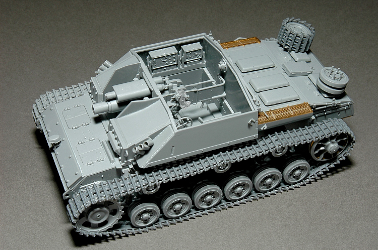
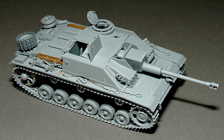
The moulding of this kit is flawlessly clean without a hint of flash. The fit of the model is equally impressive. A few problems arise if you follow the assembly instructions, I'll point those out.

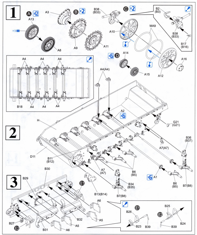
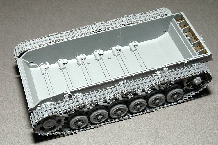
Steps 1,2 and 4 concentrate on the torsion bar suspension. The only issue to be aware of here lies within the idler wheel base mount. Leave parts B2 and B3 off the base mount and do not adhere the idler wheel on to the base mount. On step 4 adhere the base mount onto the hull and then place parts B2 and B3. Once you're satisfied with the fit, then attach the idler wheels. As Vinnie stated in his review, by removing the small locating pin underneath the swing arms, you can articulate the suspension.

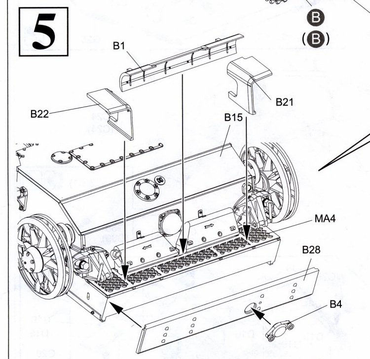
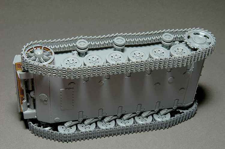
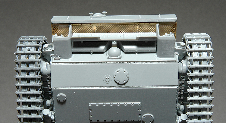
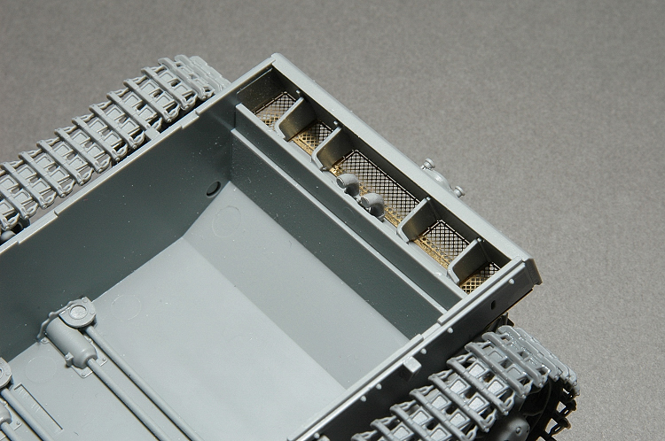
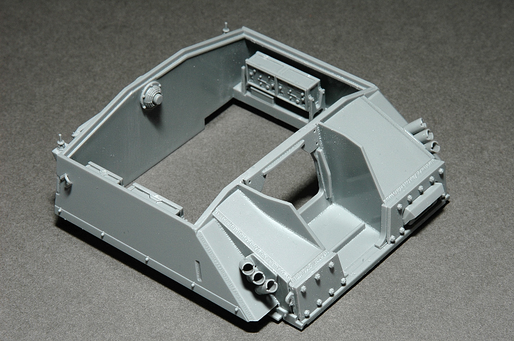
Steps 3 and 5 centre on the hull rear. A complex bit of work that once put together will mesh the mufflers, deflector plate, inspection hatch and idler base. An impressive bit of engineering.

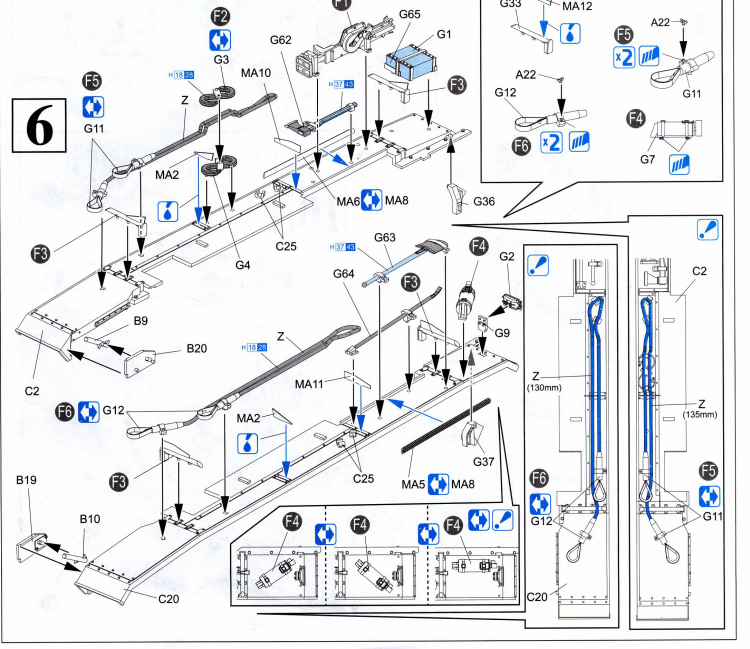
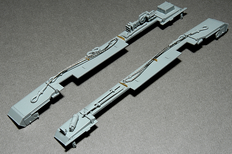
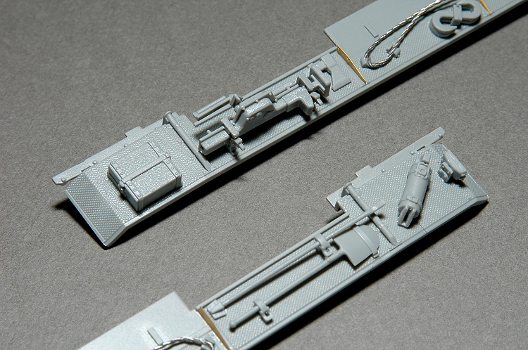
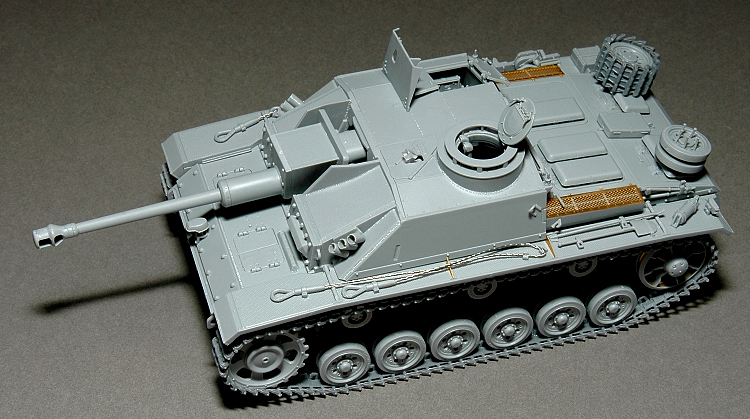
Step 6 centres on the fenders, and the attachment of the tools. A fantastic bit of slide-moulding on these fenders, finely engraved tread pattern on both sides. Almost criminal to replace these with photo-etch! Potential problems arise with the towing cables, the instruction lengths given might not work for you. I would suggest that you attach one of the end loops G12 to the metal tow cable, insert the cable in the brackets C25 and then once the second end loop is attached to the fender, cut the metal tow cable to fit and insert to the second G12 end loop. Photo-etch parts MA12 is a reinforcing triangular support which where not present on all early model G's.

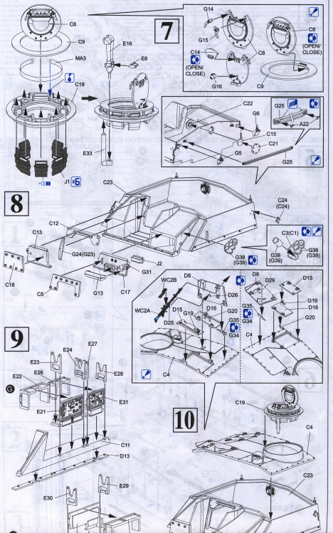
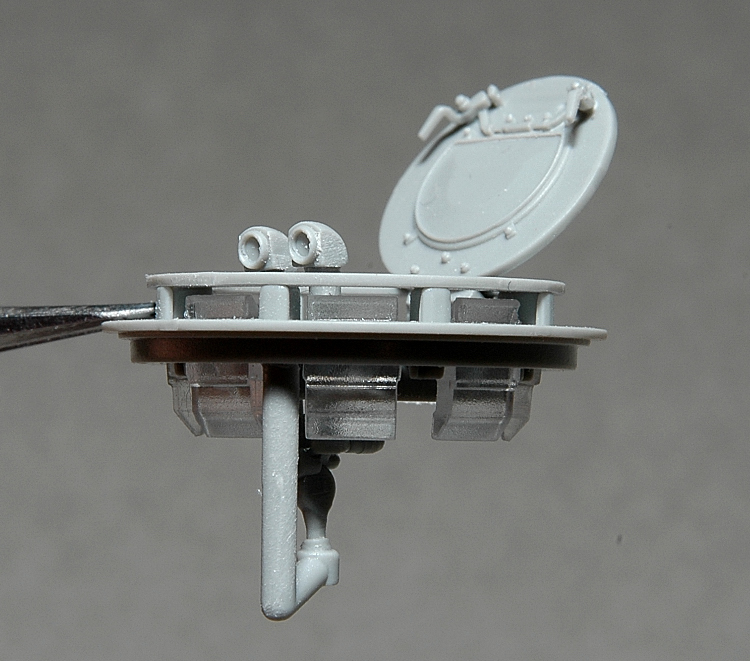
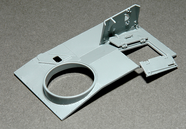
Step 7 centres on the commanders cupola, with seven periscopes which according to the Achtung Panzer No.5 is accurate, and the SF14Z scissors telescope. Part C14 has a solid plastic handle which should be replaced with wire.

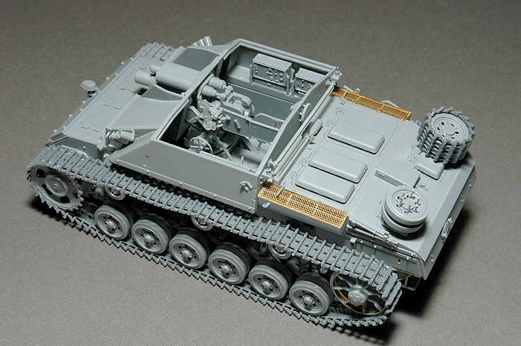
Steps 8 to 10 moves to the fighting compartment superstructure which is accurate for an early model G. The interior is accentuated with a full radio setup, receiver and transmitter. Enough detail to allow you to open the hatches without fear.

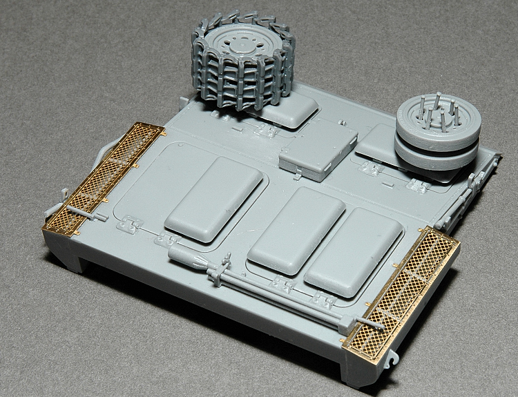
Steps 11 to 14 details the engine deck and the steering brake inspection hatches. Problem free areas that have been engineered to allow you the option of opening them up with details on the inside should you wish to add an interior.

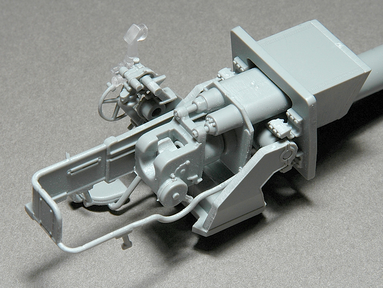
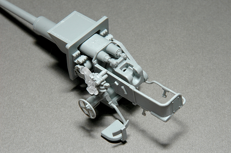
Steps 15 to 17 centres on the 7.5cm Stuk.40 L/48. The kit gives you a full breach assembly and recoil guard, all sitting on a fully detailed upper and lower carriage base. Excellent level of detail. Gunsight mount and Sfl.ZF1 gunsight round out the detail. Care must be taken on the fit of the recoil system compartment E2/E3, make sure you dry fit them in relation to assembly N (Step 16) as it is a tight fit.

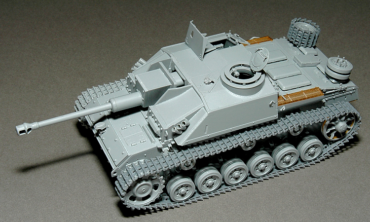
Step 18 joins together all of the sub-assemblies, which thanks to Dragon's excellence, allows you to easily paint seperately without issues. Please note that my completed model is in sub-assemblies and any gaps visible are due to this.
SUMMARY
An excellent trouble free model from Dragon. Enjoy it out of box or dress it up with Cyberhobby's upgrade sets 3832 and 3834. Highly recommended.
  DESIGN:100%
  MOULDING:100%
  INSTRUCTIONS:90%
Percentage Rating
98%
  Scale: 1:35
  Mfg. ID: 6320
  Suggested Retail: 50 CDN
  PUBLISHED: Jan 28, 2007
  NATIONALITY: United States
NETWORK-WIDE AVERAGE RATINGS
  THIS REVIEWER: 89.12%
  MAKER/PUBLISHER: 86.16%

Photos
Click image to enlarge
  • Steps_1-3
  • Step_4
  • Step_5
  • Step_6
  • Steps_7-10
  • Steps_11-13
  • Step_14
  • Steps_15-16
About Frank Portela (Clanky44)
FROM: ONTARIO, CANADA

I'm an avid modeller, with about 20 odd years of experience. I belong to a very small group of modellers here in Guelph, Ontario that formed GPMG (Guelph Plastic Modelling Group) over 12 years ago. We have our annual show (WELCOME - Wellington County Modellers Exposition) in the spring. We pride ou...

Copyright ©2021 text by Frank Portela [ CLANKY44 ]. All rights reserved.


Comments

Nice review Frank. A couple of small notes. 1. In step 11. Switch partsD23 qand D24, then rotate them 180 deg before cementing to part D5. Only one point of the spare bogie wheel tripod should be to the rear, not two as the instructions show. 2. In step 12. when adding G30 to D2 the instuctions show it upside down. 3. In step 8, do not cementpart C4 or C12. This just makes installing the gun later more difficult.
FEB 09, 2007 - 08:19 AM
Nice review! I wanted this model, but it was not yet available in the whole of Italy, according to what the shop assistant told me! Fantastic work! Looking forward to see it painted and weathered!
FEB 09, 2007 - 03:33 PM
Other small notes. 1. The jack bracket's are reversed on the instruction sheet. 2. MA6 is reversed on the directions. It goes on the other side. MA5 is not called out for, but it goes in the place of MA6. HTH
FEB 10, 2007 - 01:29 AM
Hi John, Thanks for pointing out the details I missed. Part of the learning process in writing reviews is taking carefull notes as you go along. I'm slowly learning, and will hopefully be a bit more thorough with my Aufklarungspanzer 38(t) review, which should be up soon. Frank
FEB 10, 2007 - 05:12 AM
Frank your review was super. Those were just some things I noticed while I built up the kit.
FEB 10, 2007 - 07:28 AM
I recall another thread here about bolt heads. It would seem this kit is "ripe for the casting" of bolt heads. Just something to think about...
FEB 12, 2007 - 08:05 AM
Looks like a really nice kit. I love the Stugs and Dragon seem to have once again surpassed themselves with another lovely kit. James
FEB 12, 2007 - 04:44 PM
04090 Frank your review was grate but ? how did you get your tracks to sit like that on the road wheels,
MAR 09, 2007 - 09:14 PM
Hi Cyril, Clean out all the tracks, remove any pin marks sand off any imperfections, once you have the tracks all cleaned off, start with the top run, measure the distance between two of the return rollers and glue that amount of tracks together on a flat surface, use a metal ruler to align the tracks. Use a glue that is slow setting, (I use Tamiya's extra thin liquid glue) let the parts cure together for a few seconds and then lift the run off the flat surface and glue it on the previously measured areas, between the return rollers, apply pressure to the top of the run to achieve the desired sag. Then continue adding to it, never glue the drive sprocket in place until the top runs are completed, this will ensure that your guide teeth and the sprocket will mesh. Once you have worked the run of tracks down and around the drive sprocket and return roller, continue to add to the run until all you have left is the bottom run (under the road wheels) measure the run needed and see if it fits the remaining gap in the tracks, if it's slightly off you have sufficient play within this stretch to compress or elongate the run to fit the space accordingly. Hope this helps, Frank
MAR 09, 2007 - 11:20 PM
   
ADVERTISEMENT


Photos
Click image to enlarge
  • Stug_IIIG_1
  • Stug_IIIG_1-4
  • Stug_IIIG_3b
  • Stug_IIIG_3a
  • Stug_IIIG_6a
  • Stug_IIIG_6b
  • Stug_IIIG_7a
  • Stug_IIIG_8-9b
  • Stug_IIIG_8-9a
  • Stug_IIIG_10a
  • Stug_III_11-13
  • Stug_IIIG_14a
  • Stug_IIIG_15b
  • Stug_IIIG_15a
  • Stug_IIIG_16a
  • Stug_IIIG_17a
  • Stug_IIIG_18b
  • Stug_IIIG_18c
  • Stug_III_19b
  • Stug_IIIG_19a
ADVERTISEMENT