Introduction
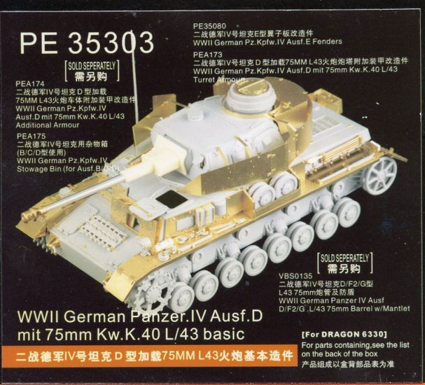
This review is for the Voyager PE set for the Panzer IV D, the up gunned version of the Panzer IV from DML, kit number 6330. This is a very extensive kit which contains well over three hundred parts. These are mostly tiny detail parts but lots of them. I will review the set moving from the front of the vehicle to the back. This set is so extensive it requires two instruction sheets printed on both sides, front and back. There are more than 30 sub-assemblies.
Review
Glacis
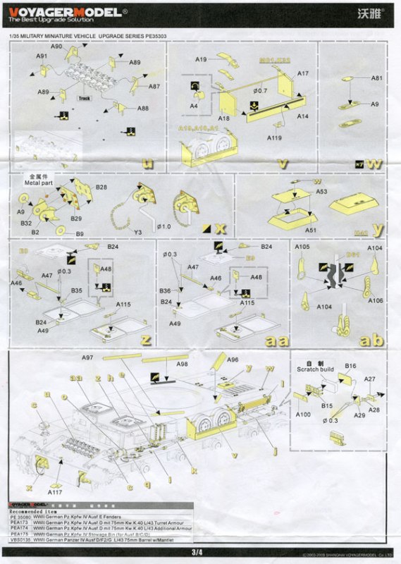
On the front glacis plate are parts for the tow brackets. The brackets are made up of thirteen parts apiece. Each bracket has a front (B28) and a back plate (B29), six bolts and the bracket itself. The actual bracket is made up of two parts each (B2 and B9 for the outside one and B32 and A9 for the inside version), and a chain (Y3). Also listed are instructions for making the pins for the brackets, although I would prefer to use the actual kit part from DML there. ** Refer to assembly drawing X in the instructions
There are seven brackets for the top front glacial plate, one for the engine hatch and six for the spare track link retainer that goes on the lower front hull. Parts A87 through A91 make up this part of the assembly which closely resembles the ones found in the DML kits themselves.
Left Side
Moving down the the left hand side of the tank going from front to back I will start with the headlight assembly. This has four PE parts. The side brackets that go around the lens housing plus a faceplate bracket (B5). The side bracket itself is made up of two pieces (B21) plus a wire (B8) that goes to the bottom of the headlight. ** Refer to assembly drawing C in the instructions.
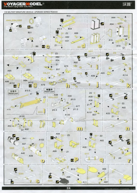
The fire extinguisher has the typical wraparound assembly we have seen from many manufacturers before. This one is on par with the ones that I have seen from DML if not better. This assembly includes five parts, one disc (A103) for the front end, a buckle for the top (parts A37 and A41), the wraparound bracket (A39) and one other smaller bracket (A40) completes the assembly. **Refer to assembly drawing O in the instructions.
The S hook bracket consist of two retainers each containing four parts. There is the main bracket itself (A95), along with the top of the bracket (A82) that has a hinge on it, and a two part lock nut assembly (Z2) one part going on top and feeding to the nut (Z1) underneath. **Refer to assembly drawing Q in the instructions.
The wrenches have the same assembly as above but each has a mounting bracket for underneath (B37) as well as the bracket for the front and rear of the wrenches (A79). **Refer to assembly drawing H in the instructions.
The two pry bars have the same PE parts for them. One is in the front next to the wrenches and the other is in the rear next to the engine exhaust. These assemblies have a front and back bracket as well as well as a three piece clamp assembly to hold the tool in place in the middle. The front and rear brackets differ depending on whether the tool is placed on the front or rear part of the fender. The parts used here are A56 and A92 respectfully. Parts A85, A86 and A112 make up this assembly. **Refer to drawing J in the assembly instructions.
The bolt cutter has the same bracket as the assembly above only slightly larger and it rests on another bracket. The parts needed for this assembly include A83, A84, and A112. The bracket it sits on is part number A114. The ends are capped with a pair of end brackets (A93) that are in one piece and require three folds to make the box end shape. This is a nice touch as you dont need to attach two pieces to make the end brackets. **Refer to drawing K in the assembly instructions.
Behind the bolt cutters is the stowage bin for the spare road wheels. This is a nice feature. The DML kits offer them in PE or plastic. But I think this one is a little nicer. It is made up of nine pieces. some wire is included in this kit but I am not sure where it goes? The bin itself is made up of two sidewalls (A17, and A18), two top brackets (A19), a front wall and front wall bracket (A14 and A119), the wire and then two small brackets (A4) that go over the wire on each side wall. The sidewalls themselves need to be folded but this is no big deal. **Refer to assembly step V in the instructions.
At the extreme rear of the fender is the taillight. This assembly is made up of six PE parts (A27 through A29, A100, B15 and B16) and then they tell you to use your scratch building skills to make the shape of the taillight itself. You will also need here a couple of pieces of rod to finish the assembly. The only drawback here is that they dont tell you how thick the scratch built part should be. **Refer to inset on bottom of instruction sheet 3.
Also on this side are two items along the sidewall of the upper hull. The first being the jack block. The jack block has seven pieces to make up its assembly. There is a support bracket for it to mount to the hull (A13). Then there are a pair of side straps (A10) as well as a buckle strap (A43 and A44) that wraps around the block itself. To finish the assembly is a handle (A54), and a lock for the bottom to lock it all in place (Q1). **Refer to assembly step E in the instructions.
On the rear of the side panel is the gun cleaning rod. This rod is in several pieces. First of all you have a resin part for the muzzle end of the rod, then you have four metal rods for the cleaning rod itself. At the end of each rod is a connector for it to fit into the next section. The brackets to assemble them are made of four parts. There is a bracket to support the whole assembly on each side(A32). Then attached to those are a three part buckle similar to the regular tool brackets but slightly different and they appear to be a little more complex. As they have a hinge to them. The parts needed here are A52, A132 and Q1 for the lock. There is also a bracket for the end of the gun cleaner(A118) and a bracket for the end of the assembly facing the back of the tank(A55). **Refer to assembly drawing on sheet 2 of the instructions.
Right Side
On the opposite side you have another headlight, the same as the other side. Next you have a tool I am not familiar with, it is apparently a claw tool that is used to adjust the tracks on the Panzer IVs. The claw tool itself is in two parts (B33 and B34). A rod is also required to complete the assembly here. Then they simply fold on top of one another. At one end is a hinge just like the ones previously listed. There are two brackets that go along with this part. One is a simple hold it and fold it in two places (A99), while the other is more like the other brackets used on the tools on the other side. It is a four piece affair with a u shaped bracket (A31) and a hinged door (A82) on top plus a two part lock nut (Z1 and Z2) . **Refer to drawing D in the assembly instructions.
Next to the claw clamp is an axe. It has a typical pair of clamps that are made up of three parts. Due to the size of the axe handle both sets of clamps are used here one of each. The smaller one(parts, A85, A86, and A112) and for the end closer to the axe head(parts, A83, A84, and A112) Then in the front it has a box that has several folds in it to make the axe fit inside to hold it in place. **Refer to drawing R in the assembly instructions.
Adjacent to that and behind that sits the crank starter. Two three part brackets also hold this in place. It sits beside and behind the jack as well. Two of the smaller clamps are used here. **Refer to drawing S in the assembly instructions.
The jack is one of the more complex assemblies in this kit. The brackets for the jack are in four parts. This is where it starts to get tricky. It is a typical u shaped bracket(A36) but there is a part that is added to the inside to make the jack fit properly(A101). Then there are is a door latch(A30) on top like the others in this kit it too has a two part locking mechanism(Z1 and Z2). Then the jack itself has a replacement in PE for the end of the jack(A7). You need to fold the four sides and secure them together to the end of the jack. Accompanying this are several other parts for the jack itself. The handle for the jack has four small PE parts that are required for the assembly if you choose to replace them. One is a small gear like disc(A50) that secures to a plate(A38) that glues to the jack. On the other side of the gear sits the long bar(A77) that is associated with the jack. On to that is secured a bolt(A120) and also required are three pieces of rod. This part of the assembly will probably require some major patience and good experience with PE. **Refer to drawing M in the assembly instructions.
Behind the jack are three replacement track links. They are secured with a four part bracket system(parts A94 and A95) just like the others, hinged at the top, only difference is that it has an extra set of folds to make the shape required. Not hard just two more folds then normal. The brackets are fixed with a nut with parts Z1 and Z2, just like the others. **Refer to drawing P in the assembly instructions.
Behind that sits one more wrench crowbar with exactly the same method and parts as used on the two on the other side.
On the side wall sits three things that have PE parts. First off front to back is the antennae mount. This has four parts that have to be mated to the plastic antennae. You need to remove some of the antennae itself so be cautious. Two parts (a pair of part number A104) have to be bent the other two (parts 105 and 106) just need to be installed into place. Not much that seems difficult with this one here. Simply remove the plastic and then bend the two side parts around a wire or piece of rod. **Refer to drawing AB in the assembly instructions.
The next part to deal with is the antennae mount rail. This is a nice touch. There are lots of parts here to make up this assembly. Again to start some of the plastic part needs to be removed. The frame is made up of two sections one left and one right so be careful as the numbers are different. A20 is for the right and A21 for the left. You need to fold one small part at the top. Then a second part is added through a very small slit in the strap itself. Careful here as these small add-ons are very small. The two of them parts A22 gets folded twice and then inserted into the two previously mentioned parts. Then a third piece (P1) is added to the outside each bracket. A four piece bracket is used for the far left bracket. It is made up of the main bracket (A59) that is folded in four places. That is secured to a second part (A60) that is made up of only one fold. To finish this assembly off a smaller part (P1) is added to the top of A59 and on the side that sits on the vehicle is a small whole in part A59 for a small rod, and anther P1 is also needed here. The rail itself has two end caps B7 for the left and A23 for the right. **Refer to step AC of the assembly instructions.
Below the antennae is the shovel. Here Voyager doesnt disappoint either. The shovel has a bracket made up of parts A85, A86 and A112. That sits on top of bracket (A66). The head of the shovel is also available in PE. It is in two parts (A11 and B13 are mated together with the handle from the DML kit. The frame of the bracket for securing the front of the shovel is made up of two parts (A67 and A68) A68 is for the top of the bracket. This part needs to be folded and bent into the proper shape unlike the DML shovel PE parts this one is not preformed. The bracket part A67 just needs to be folded in four places and installed. **Refer to step AC of the assembly instructions.
Rear
On to the rear of the vehicle. This is where the most complex part of this kit is found. Here we have to deal with the smoke grenade box. This is a very complex assembly. The assembly instructions took me a few moments to grasp the layout of this assembly. A couple of things initially looked somewhat confusing. But after studying the drawings I regained my bearings. Okay here we go
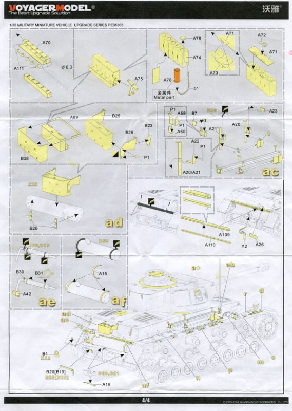
Part A70 is the first part to deal with here. It folds in five places, two ends and then folds lengthwise three times to make a box that is open on top. Inside A70 goes five smaller parts (A111) then a rod goes inside the holes of all six parts to go from end to end. To this assembly part A75 also gets secured into place. Next to deal with is part A74. A74 gets folded into another box this one slightly larger then the one just mentioned. Here we have a box that is made up just like the last one but different proportions. Then four parts (A78) go inside. This forms the chambers for the smoke chargers. The smoke changers are provided in metal parts. There are five round holes for the top of these chambers, part A76 fits on top of those five holes. Five chains (B1) attach to the bottom of the smoke chargers and the bottom of each A76. Part A71 is the lid for the box. Two pairs of hinges (parts A71 and A73) are to be attached to the back of the box. A little loop ring part A72 sits on top. Now we can attach the two boxes together. B38 now wraps around the bigger of the two boxes. Then A69 gets folded in two locations and is fastened to the back of the box. Two brackets are used to attach this whole assembly to the rear plate. Each of these two bracket are made of B23, B25 and P1(x2) respectively. The assembly parts are the same for both sides. You simply have to bend one B25 on way and the other one the other way. Then this whole assembly can be fitted to the vehicle. **Refer to step AD in the assembly instructions.
Both mufflers have replacement brackets. The smaller one has three small rings to go along with it. Part B30 and parts B31(x2) all wrap around the smaller muffler. Then the small bin underneath the muffler is replaced with a PE part (A42). Two larger straps (A15) are used to replace the plastic ones on the larger muffler. **Refer to steps AE and AF in the assembly instructions.
Parts A26 and Y2 are used for the cap on the back plate. The joint between the upper and lower rear plates also has a PE replacement set. Parts A109 and A110 make up this assembly. D29, D30 and H19 from the DML kit have replacement parts B20, B19 and B4 respectively. Parts D20 and D21 from the DML kit have a PE bracket for underneath them, part A16(x2) are used here. **Refer to inset on page 4 of the assembly instructions.
Top Hull
On top of the hull are five sections that are addressed. On the two hatches on the front, the metal ring around the turret and both hatches on the back. On the front hatches, most of the parts are internal so if you close the hatches you wont even need to use them. Both hatches use three parts underneath to manufacture the hatch assembly, One (A46) has to be folded in three places to make a box shape. The others simply glue in place with, these parts are A47 and B35,or B36 depending on the side. B35 is for the left while B36 is for the right. B35 and B36 both also have two rods that need to be inserted into their respective holes. Both sides get two other parts A115, and B24 that just simply install into place. Parts A48 and B24 are used on the outside of the hatches and A48 on the back and B24 up on top. **Refer to steps Z and AA in the assembly instructions
Parts A6, A97 and A98 are used to replace the structure around the turret ring. They simply fold into an L shape and then get installed after you remove the molded in sections. **Refer to bottom of page 3 of the assembly instructions.
For the engine access hatches there are seven two part assemblies used to replace the molded on latches. These are made of parts A9 and A81 respectively. Parts A51 and A53 round out the lower hull assembly for the PE parts. A51 replaces the kit door for the left rear hatch While part A53 replaces the lid. The two have a hinge system just like the rest of the kit. **Refer to step W in the assembly instructions.
Turret
The turret even has some very nice touches too. Let's start at the top. The copulas hatch is completely replicated in PE. The hatch is the most complicated portion of the turret items. It is broken down into many parts so here we go. The two sides of the hatch are made first by folding, and then bending the main rail around the curved portions of both parts (A61 and A63). Two parts attach directly to these parts A65 is a small bracket while part A62 is the long flat bar that sits on top of on side of the hatch itself. There are two you guessed it hinges here too. They are the same assembly for both sides. Each is made of four parts A57 and A58, as well as two pieces of rod. A57 simply gets folded on each end while A58 has its hinges folded and rolled. Then simply install the rods and place each assembly top of the hatch.
The inside of the hatch is also very nicely detailed. B17 gets fastened to the bottom of A63 along with a resin part for the padded part and the same gets repeated with parts A61 and B18 respectfully. Also added to the bottom of A61 is four part hatch handle system similar to the ones on the forward hull hatches. Parts A45, A47A64 and, B36 along with two rods are used here as well. **Refer to the first step on page 1 of the assembly instructions.
For the vision ports for the front of the turret there are two sets of vision port hatch covers. These are made up of two pairs of parts on both sides, A12 and A113 for both sides plus four pieces of rod. Once assembled these assemblies will be installed on the backside of the front plate for the turret. One piece attached to the turret the other to the visor port door itself. **Refer to step B in the assembly instructions.
The turret copula ring is replaced with PE parts as well. The ring is one part (B27) that simply gets rolled and installed into place. Two pairs of brackets made up of five parts (A8 and four bolts P1) simply get installed into place after A8 is folded in half. The section of the gun mantle that is protrudes out from the mantlet is replaced with a three part PE assembly parts A80, B10 and B14 make up this assembly. **Refer to page 1 of the assembly instructions.
Three more parts make up the turret assembly. A pair of PE parts are provided for inside the side hatches. Parts B6 are provided for these two items. Then B3 replaces the metal bracket in front of the copula. The last touch for this kit are the locks for the back of the stowage bin. These assemblies are made up of five parts respectively. A108 or A116 depending on whether or not you use the lock, then A107 and Q1. **Refer to page 1 of the assembly instructions.
Additional Voyager PE sets reviewed on Armorama can be found at the links below:
Fender Set
Stowage Bin
Conclusion
All and all this a very extensive set. A lot of work will be required for completing this kit. But for those of you with the PE experience should be able to work this kit. I would not recommend this kit for inexperienced PE builders as there are lots of tiny pieces that may steer you away from using PE in the future. But if you have the stamina to work this kit, it will make your Panzer IV D up armored kit a much nicer replica to display on your shelf.


Comments