

Hi Gareth - thats a good summary of some of the changes. My last model was when I was 11 or 12 - I believe it was an F-18. Right now Im doing a panzer iv, having completed a t34/85 over Christmas break.
Im a huge military history nut, especially ww2 European theatre, so Im doing a series of 1/35 scale WW2 tanks. Next up on the list is a tiger, then a Sherman, then maybe a Churchill. For me building is an extension of the history aspect - some day when my skills are up to it it like to do a ww1 diorama of a MkV climbing over a German trench - thats a long way off though!
Hosted by Darren Baker
My first build in 40 years...so here goes!...

GatorPanzer

Joined: January 21, 2019
KitMaker: 4 posts
Armorama: 2 posts
Posted: Tuesday, January 22, 2019 - 11:35 AM UTC

G-man69

Joined: October 17, 2017
KitMaker: 944 posts
Armorama: 928 posts
Posted: Wednesday, January 23, 2019 - 03:44 AM UTC
Hi Tom,
What brought you back to the hobby after so many years, and what would you say have been the main changes in your opinion?
You should post some images of your builds on here, would be good to see them.
When Ive finished the Conqueror build, Im going to build a diorama for it, so that will be my next build, or at least a continuation of this one.
I too want to do a WW1 trench diorama, have been collecting lots of images for inspiration, though the thing that is holding me back at the moment is being able to do justice to the figures painting-wise.
I will see how well I do with a few figures to man my Conqueror, if Im happy with the results I will then undertake the trench.
As an aside, do you, or anyone reading this post, have a clue as to what figures might be acceptable, bearing in mind it only had an 11-year service history, (1955-1966 according to wiki).
There are a number of WW2 tank crew, but would they still be acceptable for mid-50s to mid-60s?
Hope to see some of your work in here.
Regards
G

RobinNilsson

Joined: November 29, 2006
KitMaker: 6,693 posts
Armorama: 5,562 posts
Posted: Wednesday, January 23, 2019 - 03:55 AM UTC
Hi Gareth,
I think, but I could be wrong (has happened once or twice before ), that the chances of a good reply to your question about figures/crew for the Conqueror would be greater if you created a new topic/thread for this.
Maybe with a title like: "Conqueror, suitable crew figures?"
There is also a specialised forum for figures in case Armour/AFV comes up dry ....
Cheers
/ Robin
I think, but I could be wrong (has happened once or twice before
), that the chances of a good reply to your question about figures/crew for the Conqueror would be greater if you created a new topic/thread for this. Maybe with a title like: "Conqueror, suitable crew figures?"
There is also a specialised forum for figures in case Armour/AFV comes up dry ....
Cheers
/ Robin
G-man69
Joined: October 17, 2017
KitMaker: 944 posts
Armorama: 928 posts
Posted: Wednesday, January 23, 2019 - 04:11 AM UTC
Hi Robin,
Thanks for the advice on the crew figures, i will do as suggested.
Regards
G
Thanks for the advice on the crew figures, i will do as suggested.
Regards
G
strongarden
Joined: May 14, 2012
KitMaker: 730 posts
Armorama: 624 posts
Posted: Wednesday, January 23, 2019 - 04:30 AM UTC
Gareth Welcome! I echo what Tom stated, which describes my sentiments exactly. I've been lurking around here ever since finding this wonderful site a few yrs ago.
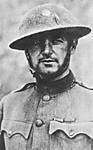
Nice start to your Conqueror build, and a great read so far. Thanks for sharing your early build fotos, my stuff was lost long ago.
You've stirred some fond memories dude, my first completed kit being Revell's trio of B17's on a bombing run complete w/ a base. Some small strange scale, but not to a kid!
Thanks for sharing
Cheers
Dave
G-man69
Joined: October 17, 2017
KitMaker: 944 posts
Armorama: 928 posts
Posted: Wednesday, January 23, 2019 - 04:37 AM UTC
Hi all,
Some minor progress today on the stowage boxes. I have completed the 4 smaller items, this time remembering to fill and clean-up the items prior to installing them on the hull top (see images below). Also note, this is the first time on this build that I have encountered any flash that is noteworthy (see 1st image below), not bad so far, and it was easy to remove,.
Flash:

Small Boxes Filled & Sanded:

Now to the difficult bit caused by my error in fixing the larger stowage boxes to the hull without first checking some reference photographs of the real tank. I did toy with the idea of trying to remove the offending boxes but, as mentioned previously, they are made from very thin plastic and I was concerned that I might do more damage than good, so decided against it.
So now I have to fill and sand the joints in-situ, again, as mentioned in my previous post it could get messy, and it did get messy it was a right ball-ache, and with limited success (see image below). I think that once I have primed the model, I will have some fine sanding to do, hey-ho, .
.
Left (as viewed) Box Filled/Right Box Sanded:

The difficulty was accessibility with both filler and files.
Below you can see a comparison of the larger stowage boxes as originally built/fitted and as filled/sanded in-situ.
Both Boxes With Join Around The Top:

Both Boxes Filled & Sanded:

One positive result, I decided to insert the turret base to see if that helps hide some of my butchery, and hey-presto it does yayyyyy (see image below), .
.
Turret Base Test Fitted:

Finally, below are all 6 stowage boxes fitted and clamped.

Regards,
G
Some minor progress today on the stowage boxes. I have completed the 4 smaller items, this time remembering to fill and clean-up the items prior to installing them on the hull top (see images below). Also note, this is the first time on this build that I have encountered any flash that is noteworthy (see 1st image below), not bad so far, and it was easy to remove,
.Flash:
Small Boxes Filled & Sanded:
Now to the difficult bit caused by my error in fixing the larger stowage boxes to the hull without first checking some reference photographs of the real tank. I did toy with the idea of trying to remove the offending boxes but, as mentioned previously, they are made from very thin plastic and I was concerned that I might do more damage than good, so decided against it.
So now I have to fill and sand the joints in-situ, again, as mentioned in my previous post it could get messy, and it did get messy it was a right ball-ache, and with limited success (see image below). I think that once I have primed the model, I will have some fine sanding to do, hey-ho,
.Left (as viewed) Box Filled/Right Box Sanded:
The difficulty was accessibility with both filler and files.
Below you can see a comparison of the larger stowage boxes as originally built/fitted and as filled/sanded in-situ.
Both Boxes With Join Around The Top:
Both Boxes Filled & Sanded:
One positive result, I decided to insert the turret base to see if that helps hide some of my butchery, and hey-presto it does yayyyyy (see image below),
.Turret Base Test Fitted:
Finally, below are all 6 stowage boxes fitted and clamped.
Regards,
G
G-man69
Joined: October 17, 2017
KitMaker: 944 posts
Armorama: 928 posts
Posted: Wednesday, January 23, 2019 - 05:02 AM UTC
Hi Dave,
I, like you, spent a good few years reading and admiring the work of people on here but, until now was a reluctant contributor, preferring silent anonymity, .
.
Thanks for the kind words, though I have to say Im struggling a bit with the build. I'm not as dexterous as i once was, and i'm making some schoolboy errors, but you learn something new every day, .
.
Its always good to take a trip down memory lane, could be an idea for a new topic 'The models we built before we hit 20' though I cant believe it hasnt already been done, .
.
I dont ever recall seeing that Revell kit, though back in the 60s/70s the choice of Revell and Monogram kits available in the UK was very limited. I do however recall reading the occasional American comic and seeing some of the adds for model kits therein, being envious and wishing I could get my hands on them,.
Thanks, and regards,
G
I, like you, spent a good few years reading and admiring the work of people on here but, until now was a reluctant contributor, preferring silent anonymity,
. Thanks for the kind words, though I have to say Im struggling a bit with the build. I'm not as dexterous as i once was, and i'm making some schoolboy errors, but you learn something new every day,
.Its always good to take a trip down memory lane, could be an idea for a new topic 'The models we built before we hit 20' though I cant believe it hasnt already been done,
.I dont ever recall seeing that Revell kit, though back in the 60s/70s the choice of Revell and Monogram kits available in the UK was very limited. I do however recall reading the occasional American comic and seeing some of the adds for model kits therein, being envious and wishing I could get my hands on them,
.Thanks, and regards,
G
RobinNilsson
Joined: November 29, 2006
KitMaker: 6,693 posts
Armorama: 5,562 posts
Posted: Wednesday, January 23, 2019 - 05:27 AM UTC
One way to avoid most of the hassle when filling/sanding/shaping is to leave the filler in its packaging and hide the package in a drawer somewhere.
I prefer to use thin slivers of styrene (plasticard or recycled packaging). Find the right thickness, cut to approximate shape and glue in place. The advantage is that it does not smear all over the place and it can be trimmed down using a hobby knife, small files or sandpaper and it usually has the same or very similar hardness as the rest of the kit, this makes it easier to avoid making bumps/hollows when sanding.
I switched to this method after exhausting my knowledge of foul language during the first attempts at using putty/fillers.
Sources for styrene sheets:
Plasticard from hobbyshops
Packaging, usually for food, with the recycle code for styrene which is the letters "PS" or the number "6" in a triangle.
Really thin styrene sheet can be found as the windows in window envelopes.
The cheap or for free stuff works for filling and where exact thickness isn't critical.
/ Robin
G-man69
Joined: October 17, 2017
KitMaker: 944 posts
Armorama: 928 posts
Posted: Wednesday, January 23, 2019 - 09:32 PM UTC
Hi Robin,
Seems all i have done these last 2 days is thank you for your advice and assistance,.
I will start to collect plastic and try your method on the next build...if i survive this one,. Though i'm certain that SWMBI (She Who Must Be ignored) will have something to say regarding my collecting something else, . But there again it's probably preferable to foul language, .
Thanks again, and regards,
G
Seems all i have done these last 2 days is thank you for your advice and assistance,
.I will start to collect plastic and try your method on the next build...if i survive this one,
. Though i'm certain that SWMBI (She Who Must Be ignored) will have something to say regarding my collecting something else, . But there again it's probably preferable to foul language, .Thanks again, and regards,
G
RobinNilsson
Joined: November 29, 2006
KitMaker: 6,693 posts
Armorama: 5,562 posts
Posted: Wednesday, January 23, 2019 - 09:44 PM UTC
Quoted Text
Hi Robin,
Seems all i have done these last 2 days is thank you for your advice and assistance,
I will start to collect plastic and try your method on the next build...if i survive this one,
Thanks again, and regards,
G
You just need to volunteer for the job of taking care of the trash and then furtively ferret through it for usable plastic. If you start off by also doing the grocery shopping you can give preference for products which come in usable packaging
/ Robin
Edit: Forgot to mention broken CD-cases. The older types contain textured surfaces. These are useful when squaring up twisted tank hulls or any other place where thicket styrene is needed.
G-man69
Joined: October 17, 2017
KitMaker: 944 posts
Armorama: 928 posts
Posted: Wednesday, January 23, 2019 - 11:53 PM UTC
Blimey Robin,
If i start acting all domesticated SWMBI will start thinking i'm having an affair, or something,.
Regards,
G
If i start acting all domesticated SWMBI will start thinking i'm having an affair, or something,
.Regards,
G
G-man69
Joined: October 17, 2017
KitMaker: 944 posts
Armorama: 928 posts
Posted: Thursday, January 24, 2019 - 06:02 AM UTC
Hi all,
A bit of a frustrating day today, maybe I should have used a Tamiya kit for my first attempt in 40 years as every review Ive read about them suggests they fall together out of the box,.
I have been working on the exhausts today, this is all covered in Step 16, and to say theyre fiddly and confusing is an understatement, though I have to qualify my comments by saying it might just be down to my inexperience again, .
.
My parts description(s) may not be accurate as I dont know the technical terms for the parts in real life, however, I hope it sort of makes sense,.
The first part(s) are the exhaust outlets, these need their rear face cleaning up as ejector pin marks will impact on how they fit to the hull (see image below), other than this, these are the easiest part of the exhaust to install.
One Untouched/One Cleaned:

The instructions seem to suggest that the 3 brackets (parts K2/K3) that support the run of the exhaust (parts K12/K13) are fitted to the hull wall first (see image below). However, these are meant to align with the 3 straps on the exhaust run, but there are no corresponding fixing positions marked on the hull.
(Step 16 Sub-Assembly:

In the end I decided to fit the brackets to the exhaust run first before fixing to the hull (see images below). This was the first really fiddly part as the male/female locating points are miniscule, trying to get the 3 brackets square and parallel drove me to distraction,.
Exhaust With Brackets:

Exhaust With Brackets:

Be careful with the small bracket at the back that connects to the exhaust outlet, it can only be fitted one way as it has a shaped male/female locator (they're dry fitted in the above images).
Even constructing the brackets and the exhaust as I have done above it still leaves you with the issue of fitting the whole sub-assembly to the hull. As mentioned previously there are no locators or even marks to indicate exactly where the brackets fit, so I chose to position them horizontally (see image below).
Exhaust Orientation:

Please note, the shape of the exhaust end piece is not symmetrical and, looking at photographs, I think (but check for yourselves, I could be wrong) it is meant to be positioned with the wider bow being furthest from the hull (see image below), this isnt obviously clear from the instructions (if anyone thinks otherwise please let me know).
Exhaust End:

The truly frustrating part to this is that at the end of the day all this fiddle and confusion is going to be hidden by the exhaust shroud/cover (see image below) which I have dry fitted to show what I mean,.
Exhaust Shroud:

Oh, the pain, the pain...I think it would have been easier if Amusing Hobby had designed the shroud with an insert fitted 10mm back from the open end, into which the exhaust end(s) could have been plugged...easy as that!
One of the shrouds has a small secondary exhaust fitted within it which, ideally, needs the end drilled out (see images below).
Secondary Exhaust Drilled:

See what i mean about stumpy fingers,.
Secondary Exhaust Location:

Step 16 has some confusing drawings, i will highlight these tomorrow, but for now my brain hurts too much to try and detail them today,.
Regards
G
A bit of a frustrating day today, maybe I should have used a Tamiya kit for my first attempt in 40 years as every review Ive read about them suggests they fall together out of the box,
.I have been working on the exhausts today, this is all covered in Step 16, and to say theyre fiddly and confusing is an understatement, though I have to qualify my comments by saying it might just be down to my inexperience again,
.My parts description(s) may not be accurate as I dont know the technical terms for the parts in real life, however, I hope it sort of makes sense,
.The first part(s) are the exhaust outlets, these need their rear face cleaning up as ejector pin marks will impact on how they fit to the hull (see image below), other than this, these are the easiest part of the exhaust to install.
One Untouched/One Cleaned:
The instructions seem to suggest that the 3 brackets (parts K2/K3) that support the run of the exhaust (parts K12/K13) are fitted to the hull wall first (see image below). However, these are meant to align with the 3 straps on the exhaust run, but there are no corresponding fixing positions marked on the hull.
(Step 16 Sub-Assembly:
In the end I decided to fit the brackets to the exhaust run first before fixing to the hull (see images below). This was the first really fiddly part as the male/female locating points are miniscule, trying to get the 3 brackets square and parallel drove me to distraction,
. Exhaust With Brackets:
Exhaust With Brackets:
Be careful with the small bracket at the back that connects to the exhaust outlet, it can only be fitted one way as it has a shaped male/female locator (they're dry fitted in the above images).
Even constructing the brackets and the exhaust as I have done above it still leaves you with the issue of fitting the whole sub-assembly to the hull. As mentioned previously there are no locators or even marks to indicate exactly where the brackets fit, so I chose to position them horizontally (see image below).
Exhaust Orientation:
Please note, the shape of the exhaust end piece is not symmetrical and, looking at photographs, I think (but check for yourselves, I could be wrong) it is meant to be positioned with the wider bow being furthest from the hull (see image below), this isnt obviously clear from the instructions (if anyone thinks otherwise please let me know).
Exhaust End:
The truly frustrating part to this is that at the end of the day all this fiddle and confusion is going to be hidden by the exhaust shroud/cover (see image below) which I have dry fitted to show what I mean,
.Exhaust Shroud:
Oh, the pain, the pain...I think it would have been easier if Amusing Hobby had designed the shroud with an insert fitted 10mm back from the open end, into which the exhaust end(s) could have been plugged...easy as that!
One of the shrouds has a small secondary exhaust fitted within it which, ideally, needs the end drilled out (see images below).
Secondary Exhaust Drilled:
See what i mean about stumpy fingers,
.Secondary Exhaust Location:
Step 16 has some confusing drawings, i will highlight these tomorrow, but for now my brain hurts too much to try and detail them today,
.Regards
G
TankManNick
Joined: February 01, 2010
KitMaker: 551 posts
Armorama: 543 posts
Posted: Thursday, January 24, 2019 - 08:17 AM UTC
Hi Gareth check out this great photo album https://www.flickr.com/photos/southvillian/albums/72157624886401674
Pictures of in service Mk I's and Mk II's, plus Centurions and most relevant, pictures of the crews.
I have used WWII British crew figures from Miniart for post war vehicles since to my eyes they look pretty close. Pockets seem to be the main things that change!
Pictures of in service Mk I's and Mk II's, plus Centurions and most relevant, pictures of the crews.
I have used WWII British crew figures from Miniart for post war vehicles since to my eyes they look pretty close. Pockets seem to be the main things that change!
Dioramartin

Joined: May 04, 2016
KitMaker: 1,476 posts
Armorama: 1,463 posts
Posted: Thursday, January 24, 2019 - 10:09 PM UTC
Courage mon brave, in the eternal fight between Man & Plastic there can only be one winner & I think you have the upper hand
although did the Plastic score a tactical victory on your forefinger?
G-man69
Joined: October 17, 2017
KitMaker: 944 posts
Armorama: 928 posts
Posted: Thursday, January 24, 2019 - 11:59 PM UTC
Tim, thanks for the kind words of encouragement, alas the war wound was not inflicted by the plastic, its down to a small hammer and a shelf
no more nails adhesive for me next time, .
Regards,
G
.Regards,
G
RobinNilsson
Joined: November 29, 2006
KitMaker: 6,693 posts
Armorama: 5,562 posts
Posted: Friday, January 25, 2019 - 12:15 AM UTC
The Handymans 10 Commandments.
Nr 7: Thou shalt not bang thy hammer on thy finger, nor shalt thou bang it on thy thumb. Thou shalt not bang it on the fingers or thumb on thy right hand nor on thy right hand.
Verily I speak unto Ye: Thou shalt bang thy hammer on the nail, blimey.
Nr 8: When thy screw doth not want to take ahold and nothing helpeth thy may be allowed to tap it lighly with thy hammer, thou shalt not bang, merily tap it lightly, blimey.
G-man69
Joined: October 17, 2017
KitMaker: 944 posts
Armorama: 928 posts
Posted: Friday, January 25, 2019 - 12:32 AM UTC
As always i'm much indebted to you Robin for your wise words of wisdom...though alas too late this time around, .
Regards
G
.Regards
G
G-man69
Joined: October 17, 2017
KitMaker: 944 posts
Armorama: 928 posts
Posted: Friday, January 25, 2019 - 12:48 AM UTC
Hi all,
I mentioned yesterday that some of the instruction drawings in Step 16 are confusing least to me they were,
In one area of the aforementioned Step it shows the small secondary exhaust (part K7) being applied to the underside of the exhaust shroud (see image below).

In another area of the same Step an inset drawing appears to show another small exhaust installed sitting alongside the main exhaust run (see image below). This small exhaust does not have a parts number, so I checked through the previous Steps to see if I had missed it, but could not find anything.

Initially I thought these two exhausts were different because the pipe outlet on part K7 is shown with a kink in it, whereas the unnumbered one which appears to have a straight pie outlet. So, I searched all the sprues to see if I could find anything obvious that Id missed. On sprue D I found a 2-part exhaust and built it, but if I installed in the position indicated it would be too large.
I then checked all the Steps forward of Step 16, and on the last Step, 31, there is an inset isometric drawing of the rear of the tank showing the oversized exhaust fitted outboard and alongside the shroud (see image below).

However, if you look at the exhaust detail its different to the one constructed, it shows 2 small exhaust nozzles as opposed to the wide multi-outlet one used on the MKII. I think it shows the exhaust of a Conqueror MK1, therefore, the oversized exhaust is not the one shown in Step 16.
So, returning to the inset drawing in Step 16, I think the small exhaust could be either Part K7 shown separate from the shroud and without the kink being represented. Alternatively, it might be that the inset drawing has been modified from the Conqueror MKI instructions but that the small unnumbered exhaust shown is from the MKI build but was not removed from the drawing when modified.
So, after much time wasting, I chose to ignore this 'additional' exhaust detail, but if anyone knows better or can answer the mystery please let me know. Short of anything forthcoming my recommendation to anyone building a Conqueror MKII, and who see this detail, would be FORGET IT, and dont waste the time I did,.
Regards
G
I mentioned yesterday that some of the instruction drawings in Step 16 are confusing least to me they were,
In one area of the aforementioned Step it shows the small secondary exhaust (part K7) being applied to the underside of the exhaust shroud (see image below).In another area of the same Step an inset drawing appears to show another small exhaust installed sitting alongside the main exhaust run (see image below). This small exhaust does not have a parts number, so I checked through the previous Steps to see if I had missed it, but could not find anything.
Initially I thought these two exhausts were different because the pipe outlet on part K7 is shown with a kink in it, whereas the unnumbered one which appears to have a straight pie outlet. So, I searched all the sprues to see if I could find anything obvious that Id missed. On sprue D I found a 2-part exhaust and built it, but if I installed in the position indicated it would be too large.
I then checked all the Steps forward of Step 16, and on the last Step, 31, there is an inset isometric drawing of the rear of the tank showing the oversized exhaust fitted outboard and alongside the shroud (see image below).
However, if you look at the exhaust detail its different to the one constructed, it shows 2 small exhaust nozzles as opposed to the wide multi-outlet one used on the MKII. I think it shows the exhaust of a Conqueror MK1, therefore, the oversized exhaust is not the one shown in Step 16.
So, returning to the inset drawing in Step 16, I think the small exhaust could be either Part K7 shown separate from the shroud and without the kink being represented. Alternatively, it might be that the inset drawing has been modified from the Conqueror MKI instructions but that the small unnumbered exhaust shown is from the MKI build but was not removed from the drawing when modified.
So, after much time wasting, I chose to ignore this 'additional' exhaust detail, but if anyone knows better or can answer the mystery please let me know. Short of anything forthcoming my recommendation to anyone building a Conqueror MKII, and who see this detail, would be FORGET IT, and dont waste the time I did,
.Regards
G
G-man69
Joined: October 17, 2017
KitMaker: 944 posts
Armorama: 928 posts
Posted: Saturday, January 26, 2019 - 01:07 AM UTC
Hi Nick,
Thanks for the link, have just had a look, there are some good images, also thank you for the comment on the Miniart figures, I have managed to obtain a set as well as some bronco and other Miniart figures that might help, cheers,.
Thanks again, and regards
G
Thanks for the link, have just had a look, there are some good images, also thank you for the comment on the Miniart figures, I have managed to obtain a set as well as some bronco and other Miniart figures that might help, cheers,
. Thanks again, and regards
G
G-man69
Joined: October 17, 2017
KitMaker: 944 posts
Armorama: 928 posts
Posted: Sunday, January 27, 2019 - 04:42 AM UTC
Hi all,
These arrived today (see image below), I just have to decide which figures will be best suited to man the tank. Some of them may need to be modified, so have decided to dry build the turret and dry fit the top hull to the bottom.
Possible Crew Figures:

I decided to dry fit the turret, FCT (Fire-Control Turret) basically the commanders cupola and the upper hull to the lower hull just to get a feel for where I wanted some of the crew figures to be positioned.
The first thing noticed is that the FTC has 4 injection pin stubs (see image below), this also applies to the main turret. The stubs in the FTC will need removing as they interfere with the fit of the turret ring, however, the stubs in the main turret could probably be left though I chose to remove them.
Inside of FCT:

Whilst dry fitting I decided to glue the lower turret bustle insert to the main turret. This left a slight seam (see images below) that needed cleaning up using a file and concealing by applying liquid cement that was stippled on to reintroduce the surface texture using an old brush (see images below).
Turret Bustle Seam 01:

Turret Bustle Seam 02:

Turret Bustle Seam Concealed 01:

Turret Bustle Seam Concealed 02:

Below are images of the dry fitted hull and turret elements.
Dry Fit 01:

Dry Fit 02:

Dry Fit 03:

It is starting to take shape as a somewhat large cold war beast,.
Regards
G
These arrived today (see image below), I just have to decide which figures will be best suited to man the tank. Some of them may need to be modified, so have decided to dry build the turret and dry fit the top hull to the bottom.
Possible Crew Figures:
I decided to dry fit the turret, FCT (Fire-Control Turret) basically the commanders cupola and the upper hull to the lower hull just to get a feel for where I wanted some of the crew figures to be positioned.
The first thing noticed is that the FTC has 4 injection pin stubs (see image below), this also applies to the main turret. The stubs in the FTC will need removing as they interfere with the fit of the turret ring, however, the stubs in the main turret could probably be left though I chose to remove them.
Inside of FCT:
Whilst dry fitting I decided to glue the lower turret bustle insert to the main turret. This left a slight seam (see images below) that needed cleaning up using a file and concealing by applying liquid cement that was stippled on to reintroduce the surface texture using an old brush (see images below).
Turret Bustle Seam 01:
Turret Bustle Seam 02:
Turret Bustle Seam Concealed 01:
Turret Bustle Seam Concealed 02:
Below are images of the dry fitted hull and turret elements.
Dry Fit 01:
Dry Fit 02:
Dry Fit 03:
It is starting to take shape as a somewhat large cold war beast,
.Regards
G
G-man69
Joined: October 17, 2017
KitMaker: 944 posts
Armorama: 928 posts
Posted: Sunday, January 27, 2019 - 05:21 AM UTC
Hi all,
I decided to see how a couple of the figures might look when installed. The figures have their heads and arms temporarily held in place with blu tack to allow me to adjust as necessarily (see images below).
Dry Fit Crew 01:

Dry Fit Crew 02:

Dry Fit Crew 03:

Dry Fit Crew 04:

Dry Fit Crew 05:

Dry Fit Crew 06:

My current thinking for a diorama is to have the Conqueror Tank being reversed out of a dug in position somewhere on the edge of a German Forest.
Two of the turret crew, the commander and loader, are looking backwards and to the sides to ensure there is suitable clearance. A driver will be positioned in front and the gunner will be standing a short distant behind the tank, guiding the it back using hand signals least thats the current theory,.
Regards
G
I decided to see how a couple of the figures might look when installed. The figures have their heads and arms temporarily held in place with blu tack to allow me to adjust as necessarily (see images below).
Dry Fit Crew 01:
Dry Fit Crew 02:
Dry Fit Crew 03:
Dry Fit Crew 04:
Dry Fit Crew 05:
Dry Fit Crew 06:
My current thinking for a diorama is to have the Conqueror Tank being reversed out of a dug in position somewhere on the edge of a German Forest.
Two of the turret crew, the commander and loader, are looking backwards and to the sides to ensure there is suitable clearance. A driver will be positioned in front and the gunner will be standing a short distant behind the tank, guiding the it back using hand signals least thats the current theory,
.Regards
G
BootsDMS
Joined: February 08, 2012
KitMaker: 978 posts
Armorama: 965 posts
Posted: Sunday, January 27, 2019 - 06:22 AM UTC
Gareth,
Sounds good to me; you might want to consider goggles for the Driver and possibly for the Commander - they would be exposed to the elements more than the others, but a minor point.
I'm sure I'm in danger of teaching you to suck eggs here but all headsets and microphones will benefit from the addition of say, fuse wire to replicate the wireless/radio cabling.
'Looking good - always a fan of the mighty Conqueror!
Brian
strongarden
Joined: May 14, 2012
KitMaker: 730 posts
Armorama: 624 posts
Posted: Sunday, January 27, 2019 - 06:37 AM UTC
This looks impressive enough Gareth, minor frustrations notwithstanding Good to see your progress, as well as the figures joining in. The winter uniforms look the part.
Have you decided on a setting yet? I'm not too familiar with Conquer cold war deployments sorry, maybe on maneuvers from one of the West German garrisons?
Cheers
Dave
Good to see your progress, as well as the figures joining in. The winter uniforms look the part.Have you decided on a setting yet? I'm not too familiar with Conquer cold war deployments sorry, maybe on maneuvers from one of the West German garrisons?
Cheers
Dave
BootsDMS
Joined: February 08, 2012
KitMaker: 978 posts
Armorama: 965 posts
Posted: Sunday, January 27, 2019 - 07:51 AM UTC
Quoted Text
This looks impressive enough Gareth, minor frustrations notwithstanding
Have you decided on a setting yet? I'm not too familiar with Conquer cold war deployments sorry, maybe on maneuvers from one of the West German garrisons?
Cheers
Dave
Dave (and Gareth and anyone else come to that!)
I'm not a Conqueror expert though I do have a completed Dragon Mk 2 and an Amusing Hobby Mk 1 underway; as I understand it Conqueror was deployed to the Royal Armoured Corps regiments in British Army of the Rhine (BAOR) on a basis of 9 x per regiment. That would enable 3 x per Conquerors to be assigned to the 3 x Sabre (ie fighting)Squadrons (companies) in each regiment. Therefore, they were there to support the Centurion equipped regiments, not too far from the way the Sherman Fireflies were deployed in WW2.
The whole raison d'etre of the Conqueror was to be able to provide an over watch to the Centurions when or should, the feared Soviet heavy tanks appear on the battlefield. This really meant the T10 series and also the AFVs of the Soviet Independent Heavy Tank Destroyer regiments such as the ISU 152s and ISU 122. At the time the Centurion did not yet have the 105mm gun and soldiered on with its 84mm, which could probably see off the T54s of the time adequately enough. Conqueror though, with its relatively massive gun, and superior optics was assigned to deal with the heavy threat.
Our American brothers deployed their M103s at roughly the same time for the same reason.
The main armament on both the M103 and the Conqueror was practically the same gun (though I don't know if the ammo was interchangeable); due the weight of the 2 piece ammunition, the Americans squeezed in an extra Loader crew member - the British - due to either design constraints or sheer parsimony (I suspect the latter) merely ordered that their Loaders should have extra PT and rations!
Some RAC regiments apparently grouped their Conquerors in a separate heavy tank Squadron and the tactical doctrine of the time appears to have been rather loose so it may be that the regiments never really learned how to deploy the tank to the best. I must disclaim any great knowledge of how this all happened at the coal face.
To me it remains a fascinating vehicle. Designed for a specific threat which was all too real during the Cold War; it also has the distinction I believe of being the only British tank whereby every crew member has his own hatch.
'Hope this helps fill a few gaps in the general run of things.
Brian
Jasperb12

Joined: July 23, 2016
KitMaker: 105 posts
Armorama: 71 posts
Posted: Sunday, January 27, 2019 - 08:02 AM UTC
That's a mightly looking beast Gareth!
Following this build with great interest. The best of luck with it!
Jasper
Following this build with great interest. The best of luck with it!
Jasper
 |

WEB HOSTING BY


Copyright ©2021 Armorama and Kitmaker Network, a subsidiary of Silver Star Enterprises
All Rights Reserved. Please read our Conditions of Use and Privacy Policy.
All Rights Reserved. Please read our Conditions of Use and Privacy Policy.