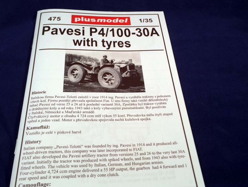
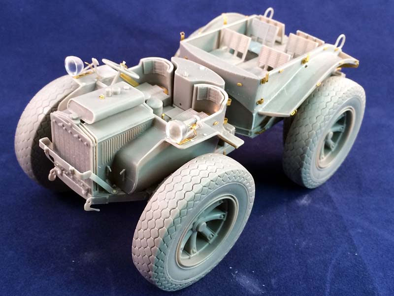
This unique looking Italian produced artillery tractor served in the period between the Wars periods and well into the Second World War with the Italian, German and Hungarian armies. Its four wheel drive capability and ability to pivot in the centre allowed movement over all types of difficult terrain, including deep sand and snow. For those interested, an internet search on this type will turn up pictures of the incredibly rugged terrain in which this vehicle was operated.
The Kit
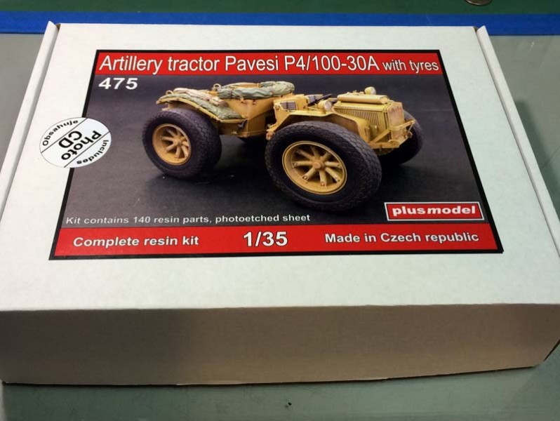
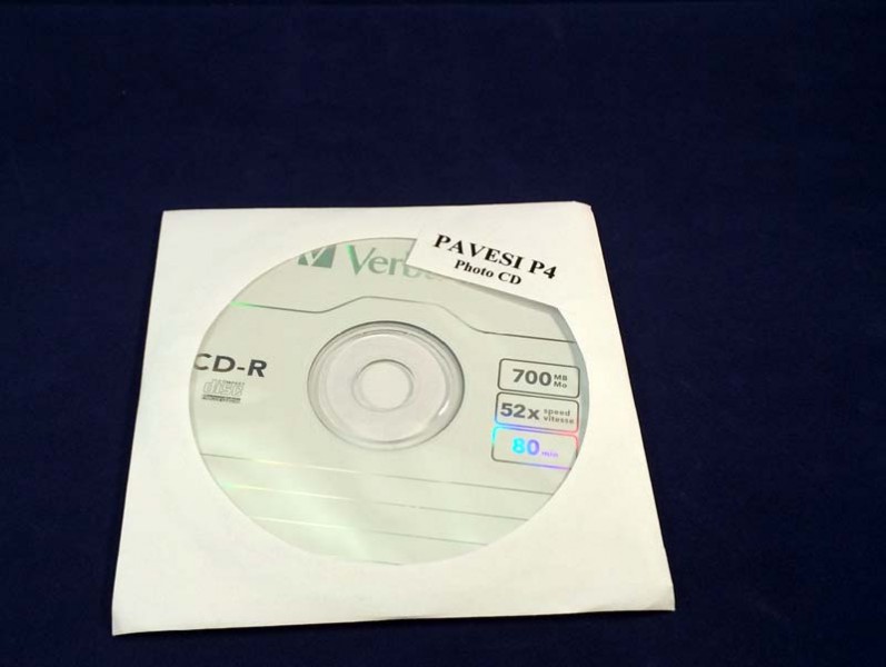
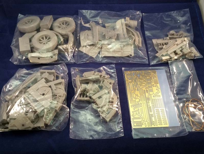
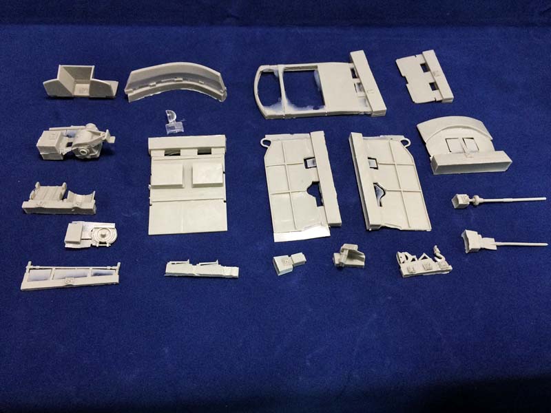
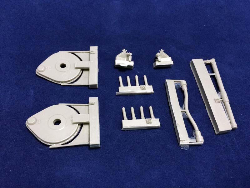
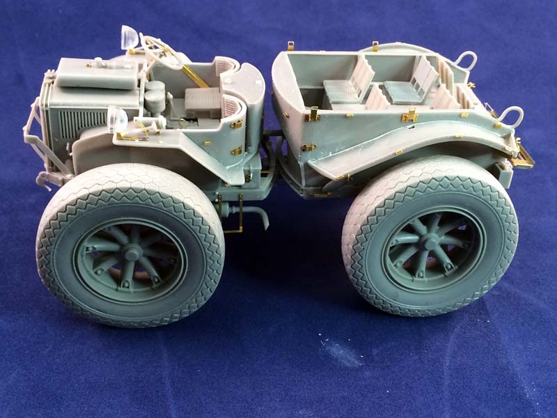
The first version of this vehicle that Plusmodel released was the P4/100-30A with the spoked, hard rimmed wheels with the flip-over traction assist paddles. This later version features the large pneumatic tires seen on many Italian vehicles used in North Africa and Southern Europe. The kit consists of 140 light gray resin parts with at least 100 more in photo-etched brass. The parts come in several plastic bags and are well protected in sturdy cardboard box with a flip open lid. There are no decals provided, but most of the photos of the P4/100 do not show any markings, so that isn't a major issue. Also included in the box are a 19 page instruction manual and a photo CD. This disk contains photos of the actual vehicle, the construction photos of the both front and rear resin assemblies and of the installation of the photo etch parts for both areas. There is also a section with a few photos of a completed model.
There are three things I want to say before getting into the details of this build. First, I really like this kit. Second, being able to see the photo CD to understand parts placement and relationships should be considered mandatory. Even though there are assemblies that seem to change from picture to picture, the photos are as essential to the build process as the instructions are. The third thing is that the kit is not for anyone but a highly experienced modeler. I have limited my comments to the points that I feel are easily missed with the information provided in the kit.
The Build
Instructions Page 2
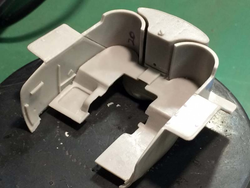
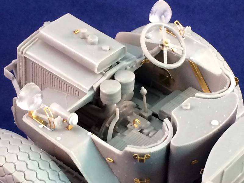
The engine and transmission were well molded, but had mold seams that had bubbles and voids which required filling and sanding. Additionally, the engine bearers in my sample had bolt heads that had to be replaced due to bubbles forming around the details. Cutting the deformed parts off and replacing them with styrene bolt heads took two minutes, clean-up would have taken much longer. I'd recommend using 5 minute epoxy to join the engine and transmission as its very easy to create chaos in you build if their alignment is off.
Instructions Page 3
Installation of the engine package in this step requires that the engine sits at 90 degrees to the frame. Shim the engine bearers if needed to get that result.
Instructions Page 4
Install part #82, the foot pedal support rod, horizontally between the frame and the side of the engine and place it in the rearmost area under the engine bearer. Any slope on this part will affect the foot pedal installation on the next page.
Parts 58 and 59 are the frame suspension supports. I would highly recommend that you hold off on installation until Page 6 when the suspension disc assemblies are installed. I didn't and I got to remove them later to correct alignment.
Part 72, the PTO shaft, is not long enough on the right angle flange end. It required a shim to get it aligned properly.
Instructions Page 5
The brake disc assemblies, parts 63, should be aligned with the brackets on part 76 and glued in place once the photo etched straps # M40 are installed. Some might find it easier to glue the discs in place first, but it is optional.
Part #M50 (the wide pedal) is very oversize and can be trimmed on both sides to provide clearance for the other pedals.
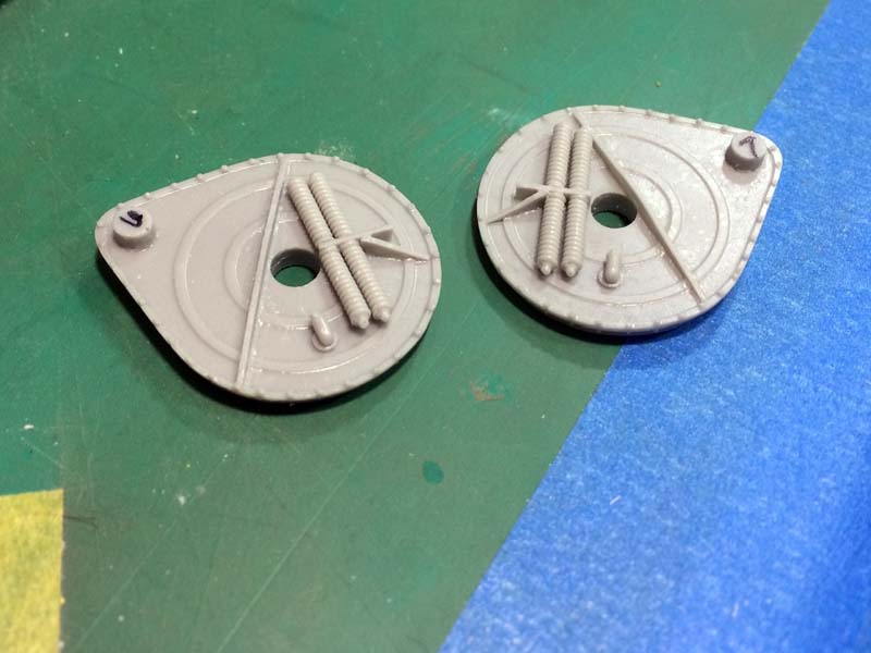
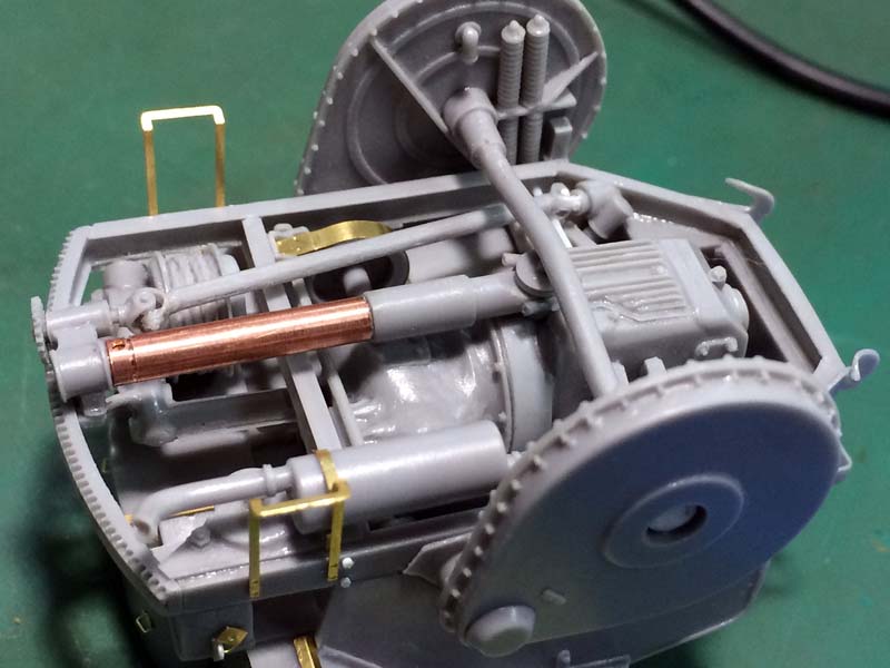
Instructions Page 6
Parts 6 and 7, the wheel mounting assemblies will require very careful clean-up. My example had bubbles at the casting block attachment point on 3 out of 4 of them which required substantial rework of the parts as they are visible when the model is finished.
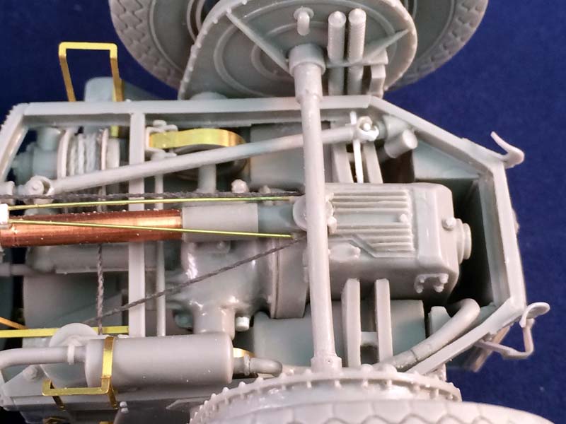
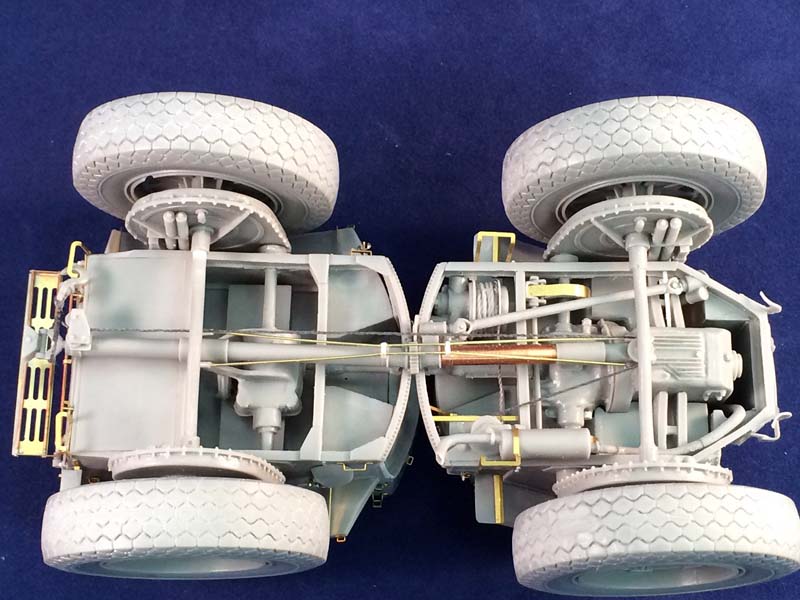
Part 16, the forward drive shaft, was warped on my example and after making only marginal progress trying to heat and straighten it, I replaced it with copper tube.
The suspension points shown on page 4 did not line up well, so I moved them to the place on the frame where the arc of the suspension disc aligned. This happened on both sides. Using the illustrations in the instructions and the photos on the CD had me positioned incorrectly so I had to remove the parts to correct alignment. I recommend that you place the rear pivot of the suspension disc in the pivot point and swing the part in an arc and find the location for parts 58 and 59.
Part 8, the suspension cross member, should only go about halfway into the disc on each side. This will provide clearance to mount the wheels later, as they share the central hole.
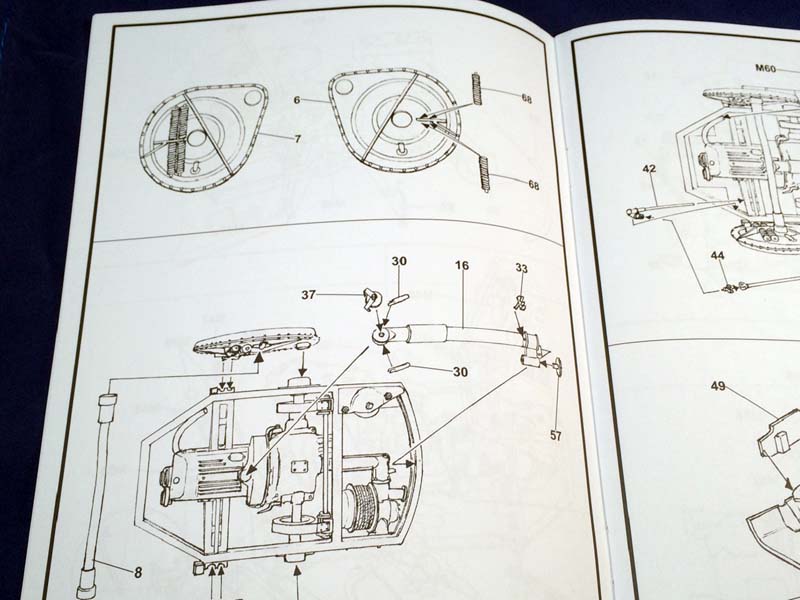
Instructions Page 7
Part 42, the steering column, should not be fit until Page 8 when the cab is installed to ensure proper alignment with the steering wheel fairing. This will also delay install of part 43, the steering coupling, and the two parts 44, the U joints.
Instructions Page 8
Parts 38 and 39 the fenders had deformations that distorted quite a few rivets. The distorted rivets were shaved off and replaced with styrene ones.
After installing the front cab assembly, install the steering column and associated parts mentioned above.
Instructions Page 9
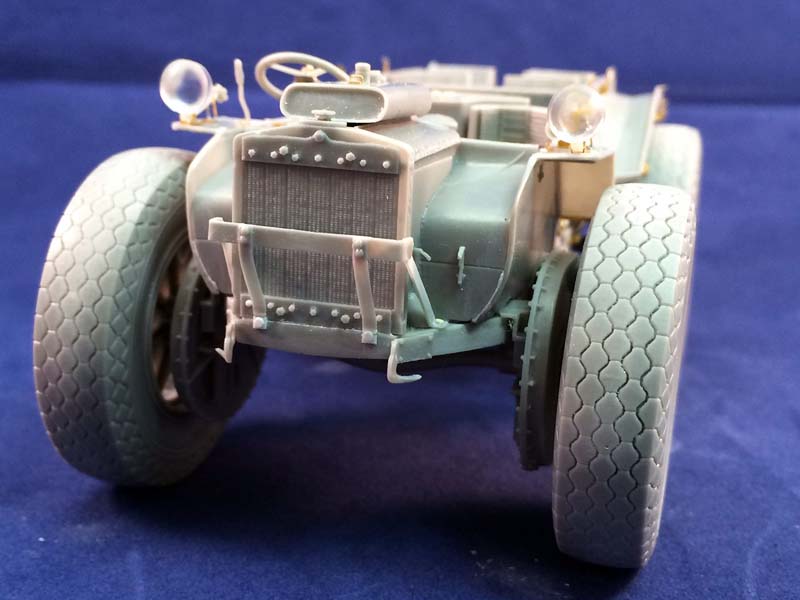
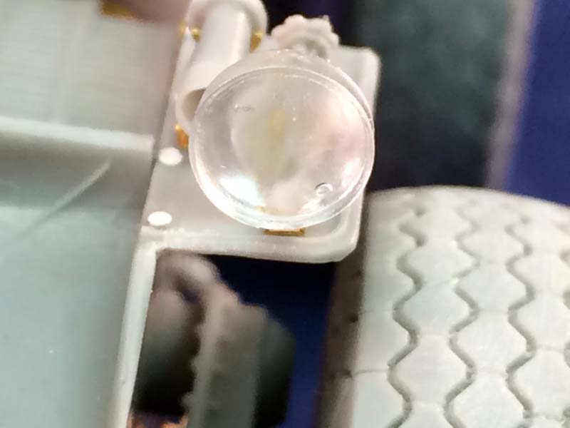
Both part 77 pieces, the clear headlights, had bubbles visible in the castings. Repair would require drilling out the bubbles and filling the holes with clear epoxy if they are shallow enough. Mine werent.
Part # M39, the hook assembly, is shown installed backwards. Photo of that area on the real vehicle show the opening for the hook should face to the rear of the vehicle.
Instructions Page 10
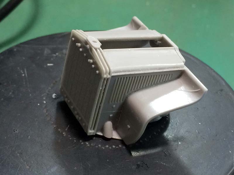
Part 74, the radiator brush guard on my kit was poorly molded. The mounting points on the rear mount arms were completely unrecognizable and where shaved off and replaced. The front arms were too short to reach the front frame cross member where they are supposed to attach, so I spliced on sheet styrene extensions and replaced the bolt head detail.
Instructions Page 11
The locators on Parts 60 and 61, the suspension mount points, place them in the wrong location to meet up with the rear suspension discs (Parts 6 &7). I chose to modify the mounts by drilling a hole aft of the rearmost mount hole and by putting the suspension travel limiting block aft of the springs. This allowed the springs to support the suspension disc without tearing up bodywork.
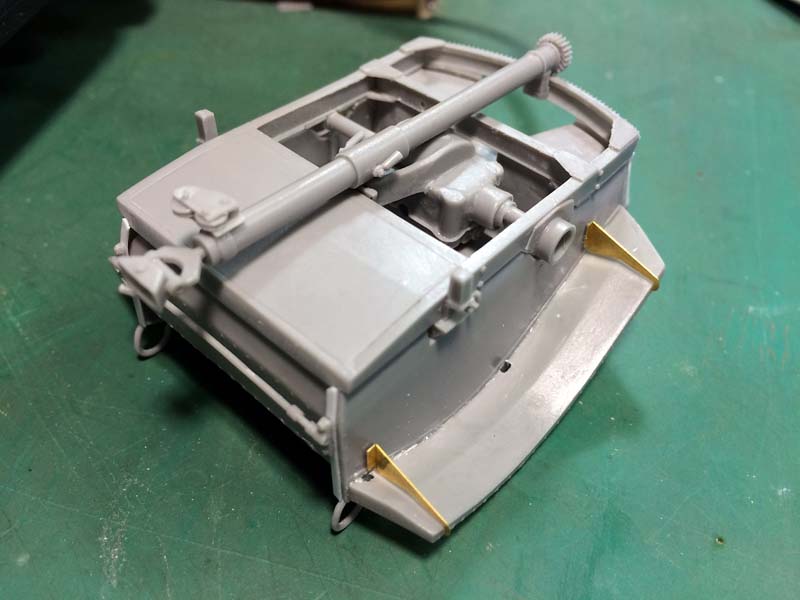
Instructions Page 12
The instructions show Part 26, the tailgate, being attached to the cab sidewalls inside the front lip of the sidewall. This part should be on the outer face. Additionally, the aft ledges on the cab rear on my sample had mold parting lines that were so large, removing them ruined the structural integrity for tailgate mounting. These were removed and replaced with sheet styrene to enable continuing the build.
Instructions Page 13
Part 86, the foot rest attachment bar, had bubbles and broke while cleaning it up. It was replaced with copper wire.
The instructions and photo CD show mounting 24 and 25, the fenders, above the cast in fairing supports on both sides. The distance to the top of the cab side panel looks correct if you do so, but there should be an attachment strip running above the fenders also.
Parts M13 and M15, the photo etched fender supports, are not shaped to meet the fenders. They leave a wide gap on the underside. Additionally, the instructions and photo CD show mounting in incorrect locations. See photos of the real vehicle to determine correct placement.
Instructions Page 14
If you have adjusted the suspension mounting points to meet the top of the spring assemblies previously, there are no major issues. If not, this is where you start cursing. Also, remember to seat the suspension cross member, Part 8, just far enough to allow the wheels to be installed.
Instructions Page 15
The instructions show the tail light is part #100. The instructions should read #23. With that said, the instructions show the clear part being installed behind the mount bracket, part M33, and protruding through. I haven't been able to find a picture of a P4/100 with a light assembly like that. It may exist, but I managed to send both of the clear parts flying to unknown regions so, I said enough is enough and turned a replacement part out of brass in the correct shape on my lathe.
Parts M27, the wingnuts, need a pin to attach then to the model, otherwise they magically remain attached to the tailgate hasps.
The same problem exists for the wingnut on the pick axe mount M31.
Instructions Page 16
The foot rest, part M11, has holes for support rods, but no rods are provided. This feature is very noticeable, so I used copper wire to create them.
Part M29, the shovel attachment bracket, should have a wingnut. Its provided on the photo etch sheet, part M27, but not shown in the instructions. It too needs a pin to support it. The shovel, part 70, has a handle which is too long.
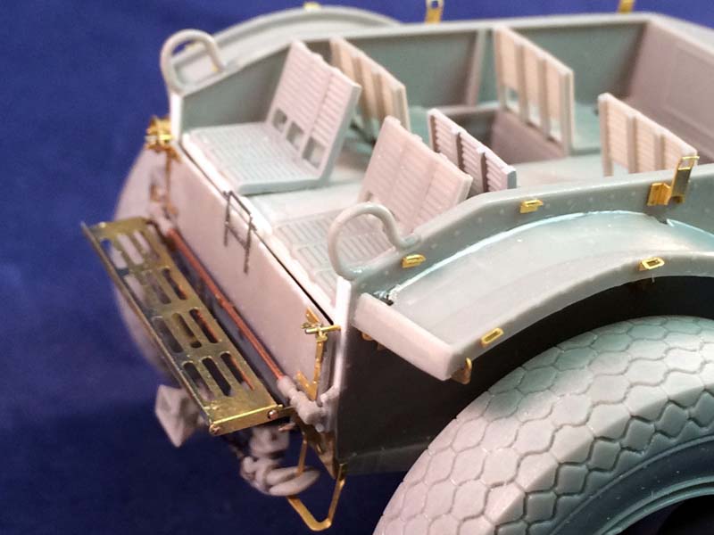
Instructions page 17
The rear seats, parts 13, had some bubbles that caused problems. One of mine had a large section broken off and another area missing. I made repairs using sheet styrene and super glue.
Instructions Page 18
The wire provided in the kit to run to the connectors on both sides of the drive shafts is way too large. I replaced it with .015 inch brass wire.
Parts 97 and 98, the canvas rolls on the fenders do not fit with the photo etch canvas supports installed. These parts will require substantial modification to make them fit, and I didn't intend to install them on this kit, so I moved on.
Instructions Page 19
The wheels went on fine, but one of them had a chunk missing from the rim. Sheet styrene was used to make the repairs again.
Conclusion
Even though Ive provided a laundry list of things that need attention, I don't want you to get the idea that I don't like this kit, I do. It has the strengths and weaknesses common to all resin kits I've seen; tremendous detail and craftsmanship offset by the inevitable problems that a short run resin casting process generates. The resin used to manufacture it was a pleasure to work with. Its flexible, sands very well, and machines very well. Unfortunately, bubbles, mold seams and warped parts are likely to be present and will take time and patience to rectify. All parts must be carefully cleaned up to fit as intended, and they must be test fit repeatedly. Sometimes youll need to look two or three steps ahead, and move back and forth between steps to achieve a desired result. I don't lay these issues only on Plusmodel, as I believe dimensional stability is one of the major limitations of the resin media. If you get a perfect resin kit, that has none of those issues, it might be time to play the lottery!
The subject matter of this kit is somewhat esoteric, which is a great plus for me. You definitely won't see 12 subtly different versions of this Italian artillery tow vehicle sitting next to one another on very many display tables. The price of the kit is $150.00 to $220.00 US, and is definitely on the more expensive end of the modeling spectrum. This will understandably put off a rather large portion of the modeling community. Never the less, if you are willing to take the financial plunge, are a very experienced model builder and are willing to spend the time needed to work through some challenges, it builds up into a truly eye-catching model that can showcase your craftsmanship.
SUMMARY
Highs: Great detail, great resin, unique subject matter, photo CD.Lows: Expensive, bubbles, some warped parts and suspension fit.Verdict: Great subject, well presented, but not for the casual or intermediate level builders. With proper care and attention to detail, this could be a show stopper.
Our Thanks to Plus Model! This item was provided by them for the purpose of having it reviewed on this KitMaker Network site. If you would like your kit, book, or product reviewed, please contact us.
Thanks Roman. It was a very enjoyable build. The only real issue I had was to keep as many parts as possible removable so I can try and paint it later on. It's still going to be rough painting the internal engine bay and such, but it will look good when I finally tackle it.
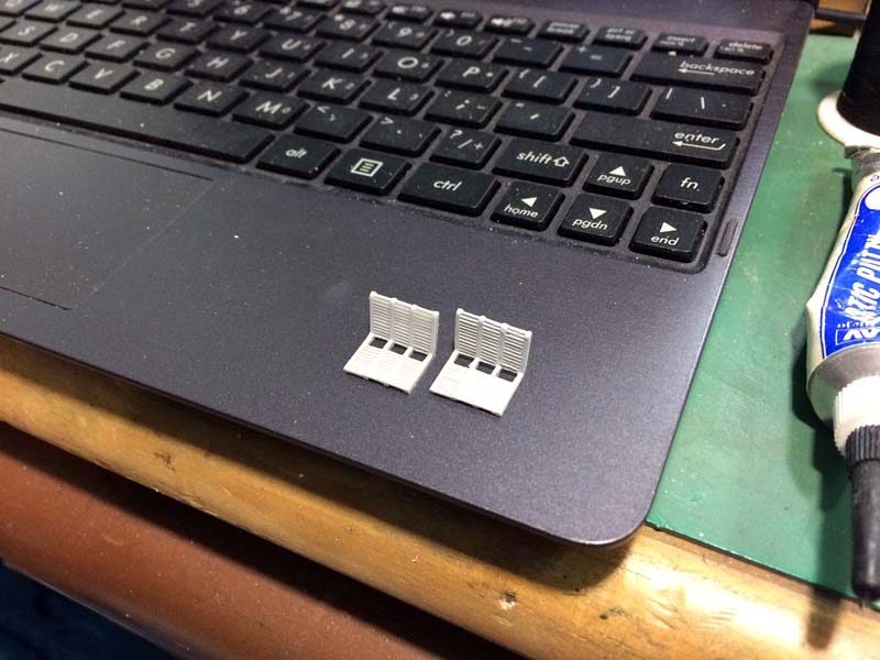
Paul H
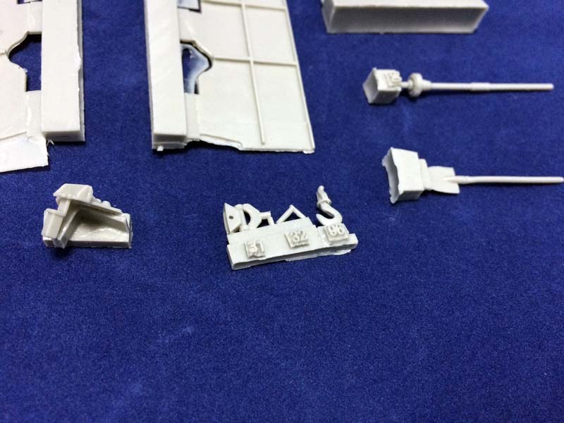
I will say, that even though some larger items had bubbles, the small parts, which help create the sense of realistic detail, were cast very well overall. Some of the companies who do computer mastered parts may be able to do better, but these masters had some very good hand-done workmanship.
Cheers,
PH
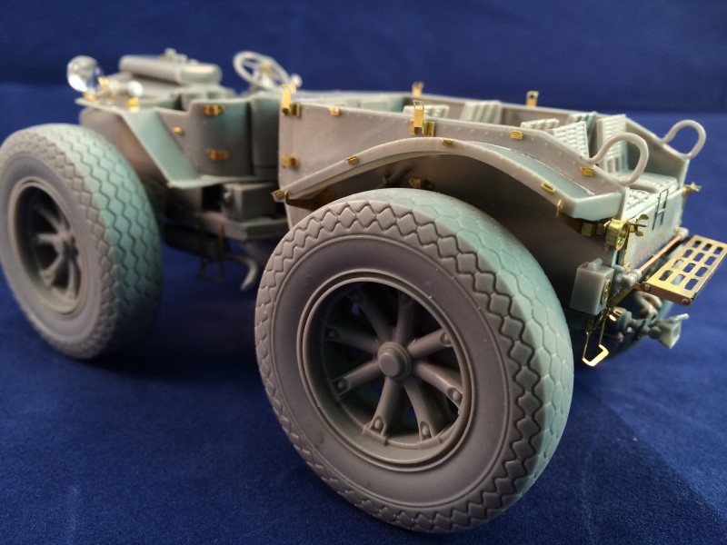
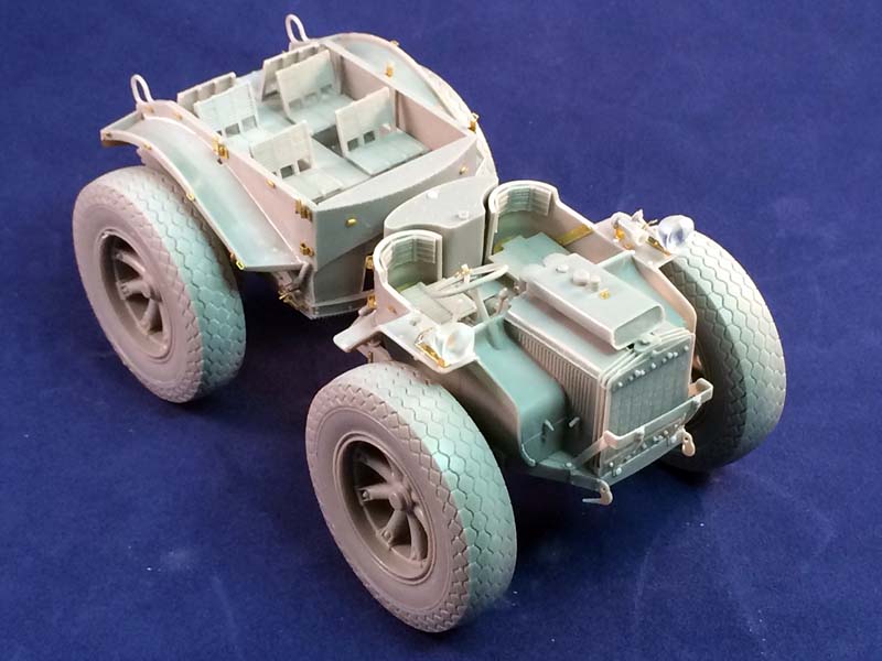
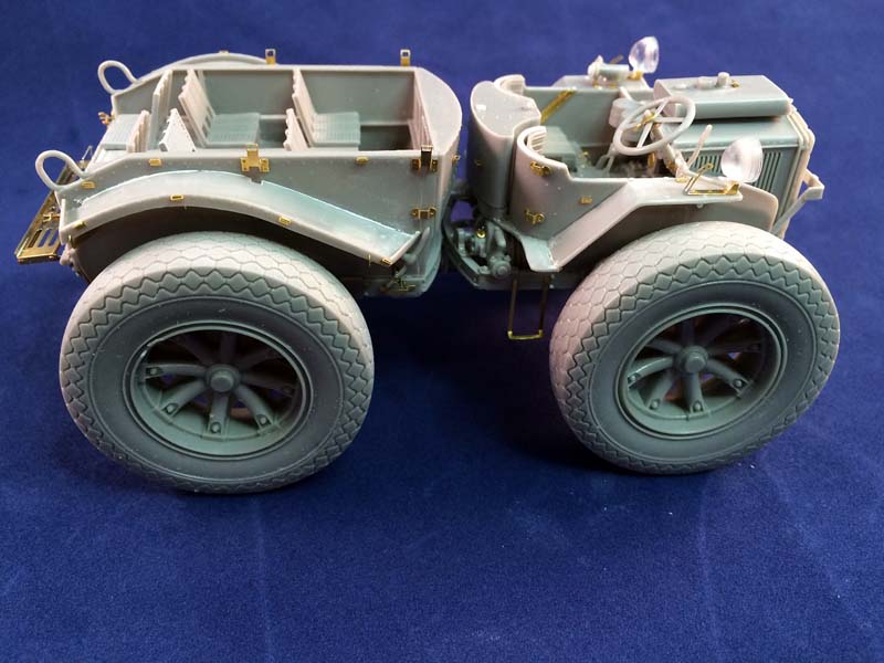
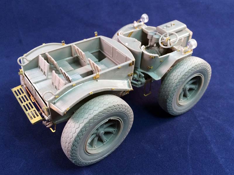
Here is the finished Pavesi P4 by Plus Model. I had three projects to complete before I could finish this piece. Since I built it for an Armorama review, I didnt have time to paint it in subassemblies as I normally would. This one was painted as a complete unit and I can assure you I will be going back to subassembly painting on my next project!
Cheers,
Paul H


Comments